

altium designer signal integrity video
How good is Altium for signal integrity? This is a question I get asked a lot. The price is right – you basically get the SI simulator for free as part of the schematic/layout/mechanical etc. package.
With cheap comes natural skepticism. We are used to fairly expensive dedicated SI tools from the big players like Hyperlynx from Mentor and SigExplorer from Cadence. So just how well does this cheap simulator in Altium Designer handle realistic simulations? I decided to do a few comparisons to test out the Altium Signal Integrity simulator. This is Part I of that test.
For this test, I picked a simple analysis of one 74ALVC244 output (can be tri-stated, but I want to look at the output enabled case only) driving one of the inputs. All operating off a 3.3V supply. And yes this is a very simple analysis – but also very similar to what you would do with the latest DDR memory device or whatever is hot for you right now.
Can't remember a 74ALVC244? Here is an example datasheet from TI: http://www.ti.com/lit/gpn/sn74alvc244
My initial thinking is: "This is a fast device, but is it fast enough to require a series termination resistor?" and "What would the ideal series termination resistor value be?". Both questions need a quick and decent but not obsessively accurate answer.
Sketch up the circuit
Cadence calls their tool SigExplorer in OrCAD PCB SI (we are on version 16.5 here). The sketch for the analysis is set up like this with the I/O driving a pulse into a transmission line (ideal 0.5ns, 50R) to the input.
Note: You can click all images to have them blown up in a more readable size.
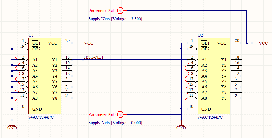
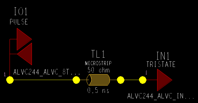 Altium Designer is different. In Altium you have to draw this with the actual schematic symbols and as a minimum connect power and ground with special net information parameter set symbols.
Models from the IBIS file are loaded and attached under the schematic library symbol. In this process, I select the TYP models, as Altium, unfortunately, requires you to select the process corner when the IBIS file is imported – more on this annoyance later.
The length of the transmission line is set in a dialog box, where all unrouted nets are given the same length and impedance:
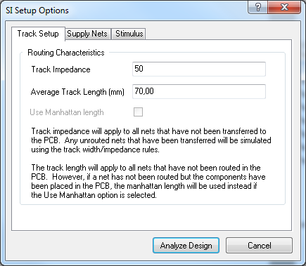
This is obviously less flexible, but sufficient for this simple analysis.
Simulation results
Now with the simulation sketched up, I want some simulation results. There are three relevant results for the SLOW/TYP/FAST corners of the driver. This is the 3 process corners:
- SLOW = Low supply voltage, high temperature
- FAST = High supply voltage, low temperature
- TYP = Both at typical/normal levels
I want to see TYP for designing the optimum series termination resistor. But I like to see FAST/SLOW also because it tells me how bad this could go. So here are the results are shown with the SigWave tool from Cadence:
It's pretty obvious that the input diode is clipping the waveform in the low state, maybe that puts too much current through that diode. I may want to check that later. Also, there is a lot of overshoot for both rising and falling edges. Maybe that's bad as well. We look at that later – now let us try Altium and see how the simulations look in that tool.
For a similar analysis and easy comparison to the earlier Cadence analysis, I had all unrouted transmission line impedance's set to 50R and the length of the transmission line set at about 0.5ns or 70mm (yes, you can use mils too). Then I press the button and get the result dialog box.
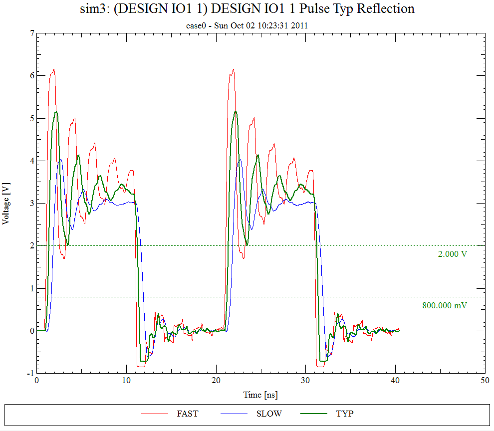
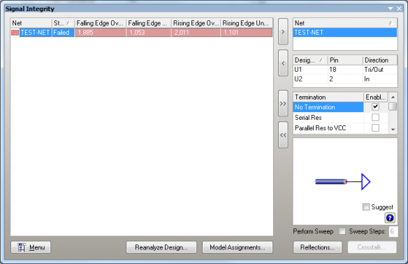 At this point, it's obvious that Altium thinks this is no good – but I want to make my own judgment by looking at the reflection waveforms. This is set up to make a comparison to the simulation with Cadence easy.

If you want to compare with the previous simulation on Cadence, this should be compared to the TYP curve (shown in green).
They are clearly not identical, but close enough. The overshoot I worry about on both falling and rising edges come out pretty much the same on both tools.
Just using the Altium tool I still have no idea how crazy this device gets at the process corners. I could import the IBIS models again this time selecting either SLOW or FAST and repeat the above, but that's a bit too cumbersome for me so I cross my fingers and promise myself to do that check later in the process.
Conclusion – Part I
For a simple analysis like this – so far Altium is up to the job. The simulation results are comparable. The UI is clearly different and less flexible in Altium, but not to a point that really matters.
Watch this space as the story continues in part II.
Q: Would SI simulations like this one require you to use the full actual part symbols in your ideal tool?
PS: Note that I will be happy to continue my exploration of Altium signal integrity features if someone will lend me a license for a while… 🙂

Rolf V. Ostergaard, M.Sc.EE. has worked with signal integrity in many different projects since working for 3Com in 1998 as a colleague to Lee Ritchey in Silicon Valley. While building a consulting business focused on advanced electronics and embedded software in Denmark, Rolf has been helping numerous companies with signal integrity and power integrity both as design, simulations, coaching, measurements, and troubleshooting. He started conducting training in SI in 2004 and has trained hundreds of engineers, which lead to founding EE-Training to further expand this.
You can hire Rolf to do signal integrity training and consulting worldwide and remote.
altium designer signal integrity video
Source: https://ee-training.dk/simulation/altium-signal-integrity-tool-part-i.htm
Posted by: goodmanwheroulatis1952.blogspot.com
0 Response to "altium designer signal integrity video"
Post a Comment